Table of contents
The issue
An RFID apartment building access control system is not working. The controller is seeing random IDs each time a tag is read.
The inventory
- 1 x C3-400 ZKTeco RFID Multi-Door Controller
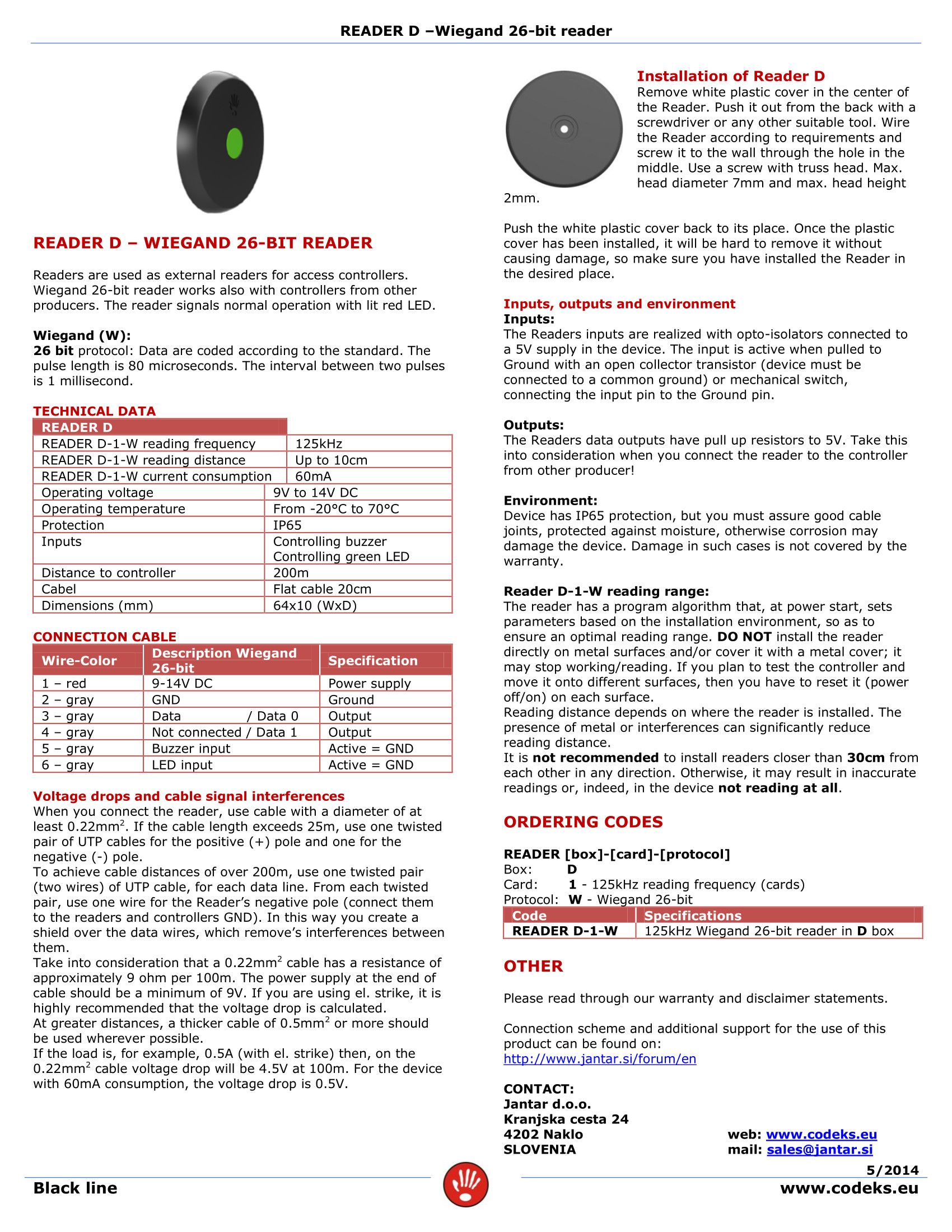
- 6 x whitelabeled, seemingly no-name, wiegand-protocol tag readers “1000-EM”
- 3 x doors (2 readers for each door)
- ~100 m. of UTP cable going to each door/reader pair
The investigation
Controller
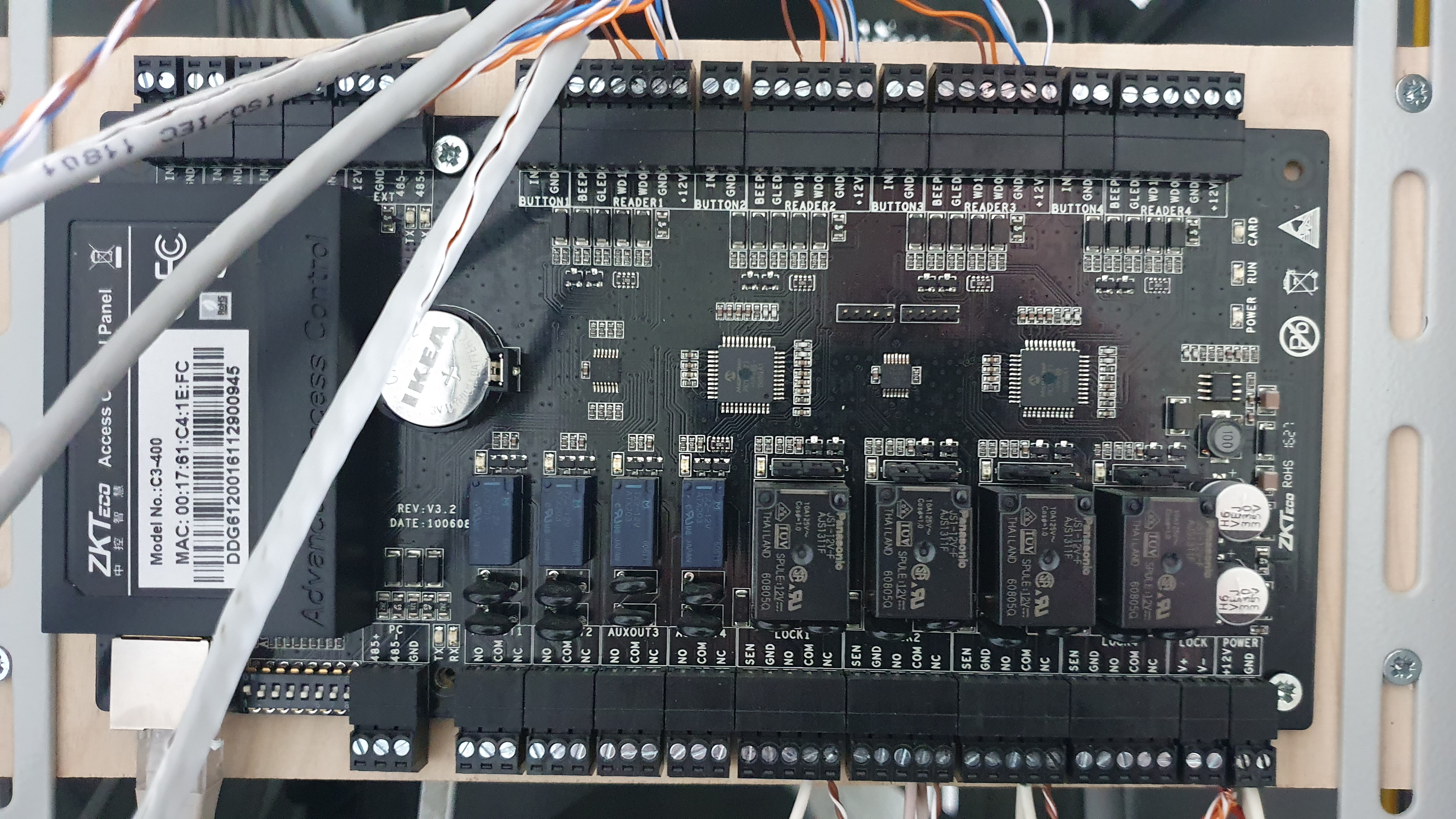
The controller setup I found:
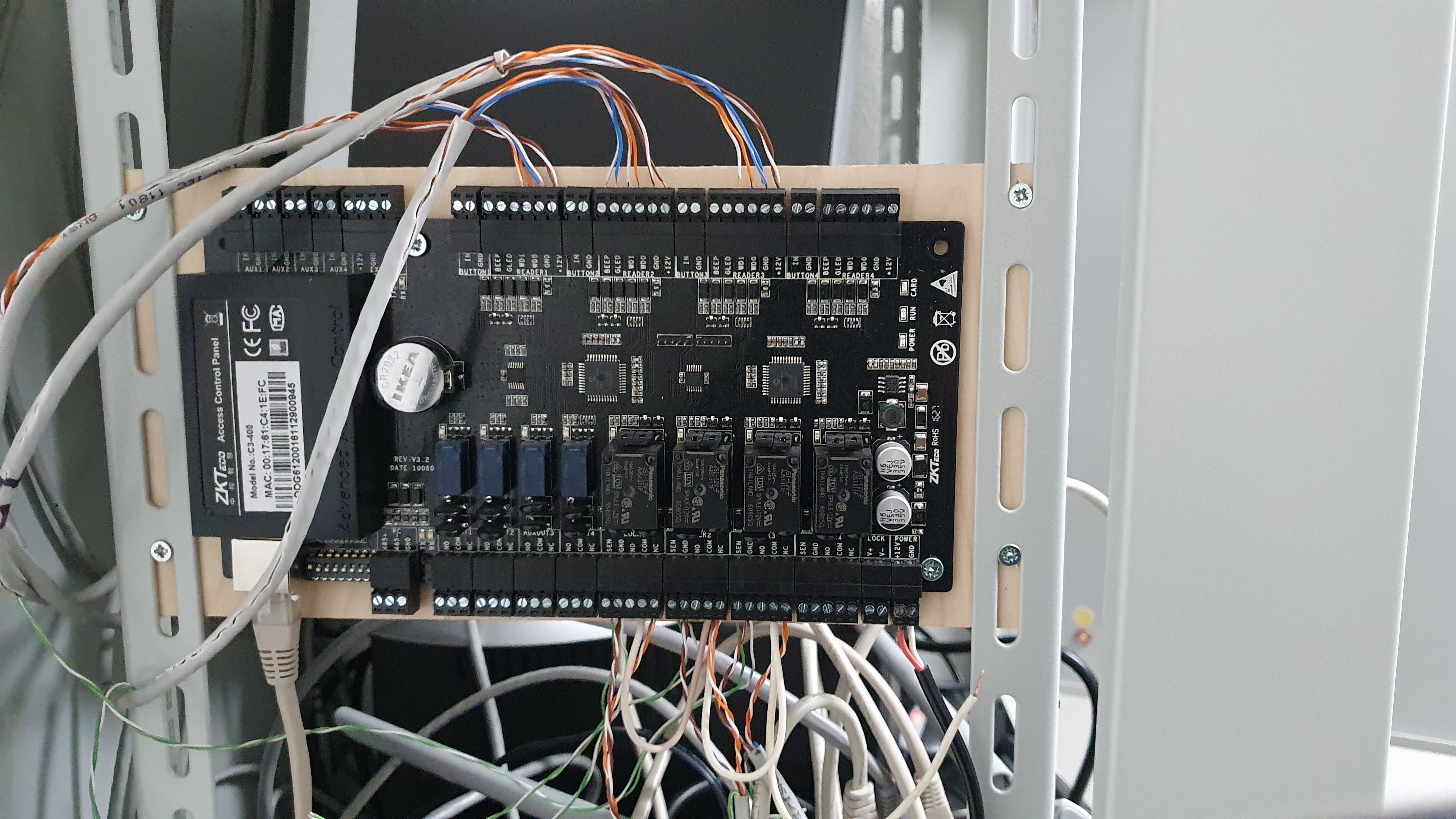
At the bottom: the brown/brown-striped cable pairs go to the V- terminal of the magnet locks. While orange/orange-striped go to the V+.
At the top: cables go to the Wiegand readers. Reader 2 has some more optional lines connected.
Readers
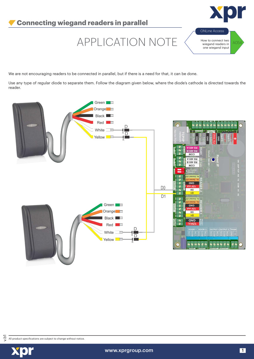
The readers are mounted near the door, both side of the wall and share data lines.
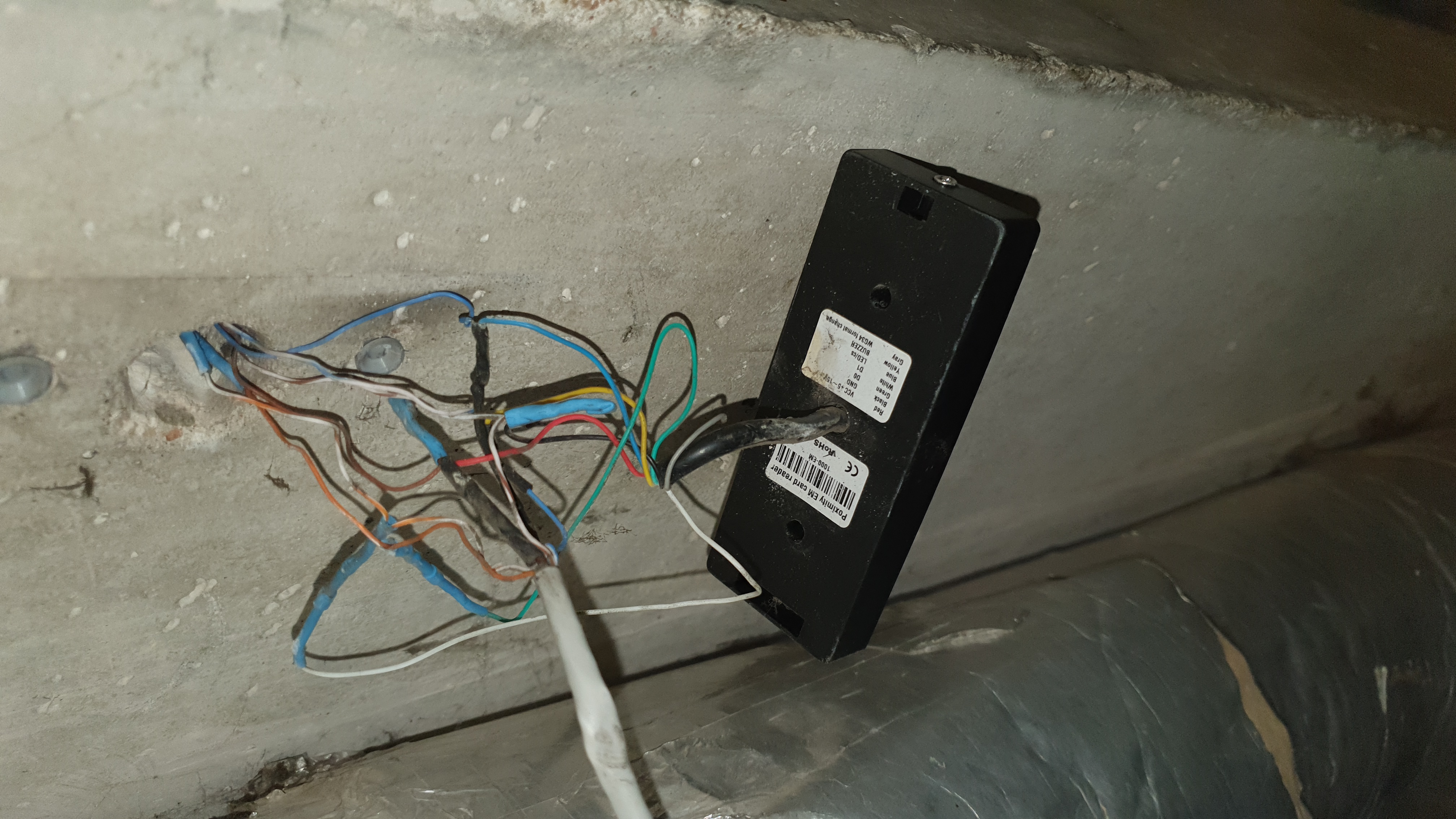
To enable data line sharing - diodes are placed on the D0 and D1 lines.
The diodes I found installed (at least for the one line I checked) were HER107.
The fixing
Doubling up data lines
You can see from investigation phase, that the power lines were doubled for the readers (GND and +12V). Expecting a better connection, I changed that to have the data lines doubled instead. The result was the same - garbage data. Seemingly nothing changed.
Poor-man’s shielding arrangement
Looking at it further - I noticed that the data lines are from a single pair - orange for D0 and orange-striped for D1. That might cause interference between them, which would degrade the signal & would be a reason for garbage data received at the controller.
The cable distances are below 200 m, but still - I used a single line for +12V and moved the data lines to separate twisted pairs and connected a single cable from each twisted pair to GND to act as a “poor man shielding” for the data line. So single cables for +12V, D0 and D1 and 3 x GND cables with two of them as shielding for data lines.
Diodes with better specs
I tested the new cable arrangement and I actually managed to get data from a single reader, but it was flaky - only about every second/third transmission got to the controller. When I connected the second reader on the lines - it went crashing down and garbage again.
The shielding document also talked about voltage drops, so I investigated how do the diodes affect the voltage.
I used UF4007 diodes and the data sheet for them shows a 1.7 volt forward voltage (i.e. voltage drop), which for the reader, I imagine, would be shit-ton enough to cause issues.

The original HER107 diodes had the exact same voltage drop.
To combat this, I looked for more appropriate diodes and found them - Schottky diodes, specifically the 1N5817.

The voltage drop is a more manageable 0.45 volts with RMS voltage and current specs more than enough for the task.
With this setup - the controller is now receiving the correct data, with no misses!
Connecting the door magnets
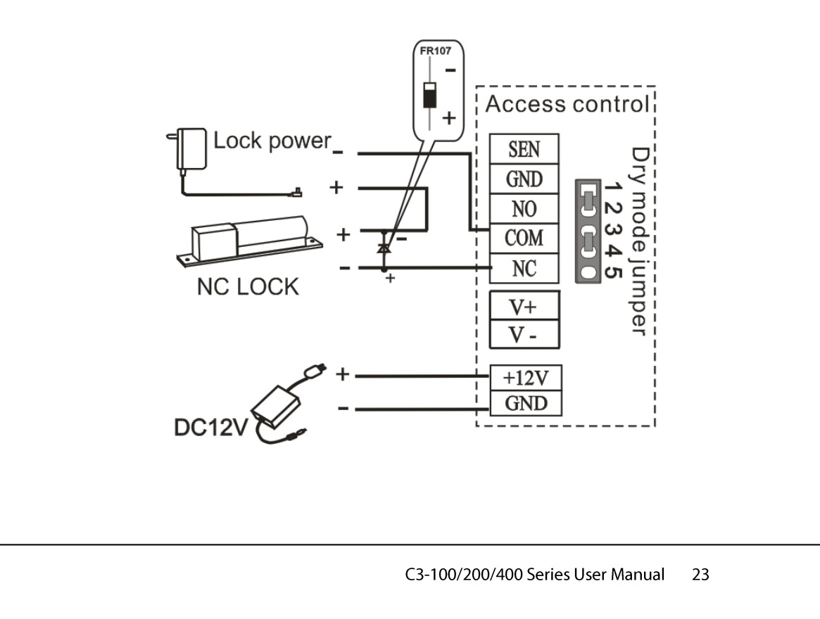
Looking at how the magnets were connected to the controller (V- to GND, V+ to NC) - I found no match for that arrangement in the controller’s documentation. So I removed those cables and connected as per the “External power supply for NC lock” diagram.
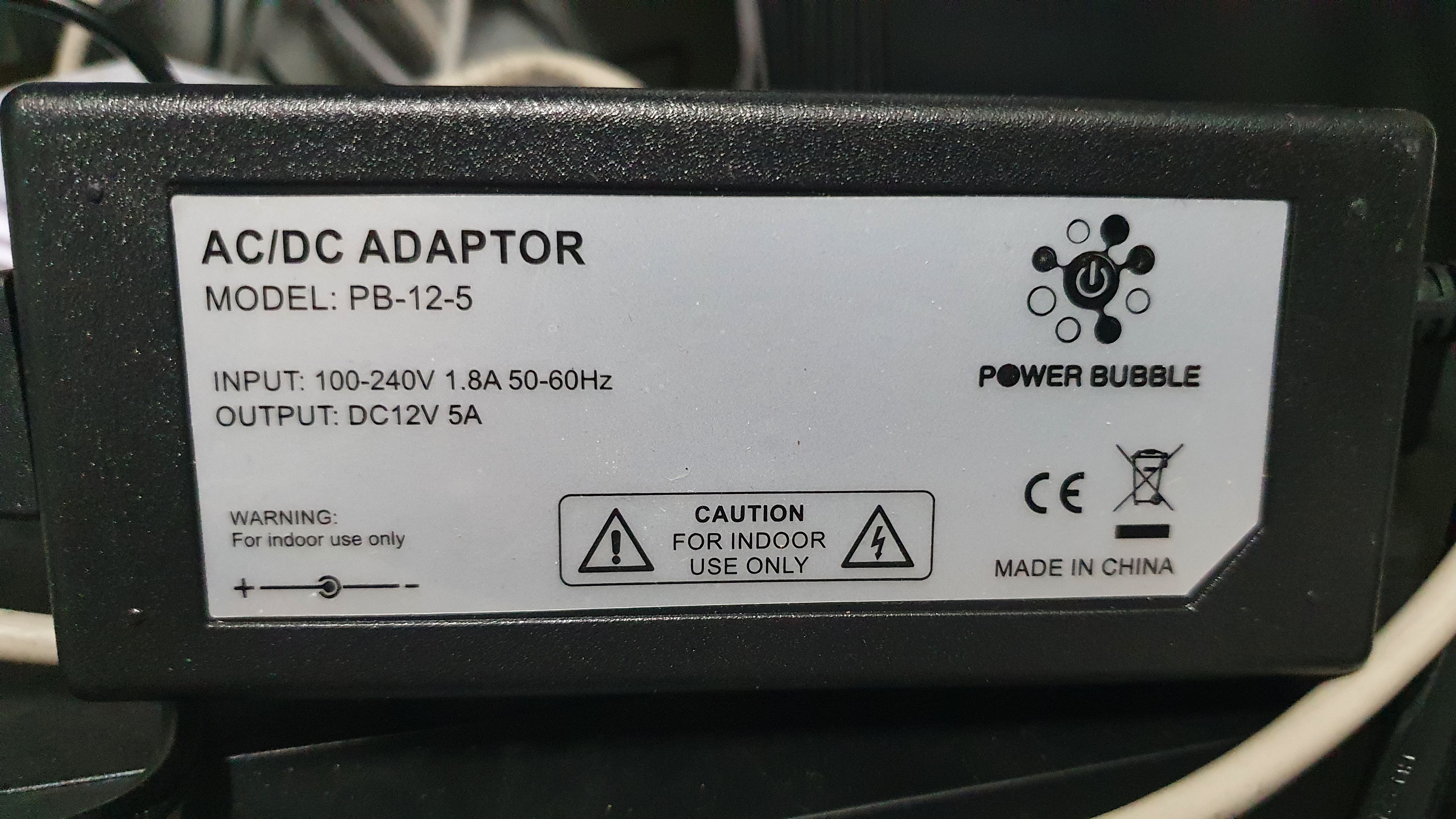
The power supply is shared between the readers and locks, but it is 5 amps, so should be enough.
Managing the controller
The software that was reported working with this specific controller was ZKAccess. I used the 3.5 version of the software, and as much as I tried - I couldn’t get it to connect to the controller.
Only after a neighbour suggested setting the timezone of the OS running the software to “China” - I’ve set it to “Beijing” and it connected straight away! Amazing.
Conclusion
The final wiring on the controller:
- The controller management software needs a Beijing timezone set on the OS to detect the device!
- Using an electronics component (diode) rated higher in one parameter (voltage, current), might have an undesirable trade-off in a more important parameter (forward-voltage, meaning voltage drop), which can ultimately break the system.
- Sending different signals over a single twisted pair will be rife with interference.
Further action
- The controller wiring mentions adding diodes near the locks to “protect the access control system against self-induced electromotive force generated by an electronic lock at the instant of switching off/on”. Might look into that to preserve the controller’s longevity.
- Figuring out what the optional wires for the readers are might be interesting.
- Connecting additional peripherals, like door lock status sensors.